I have been designing kayaks and accessories of all kinds since 2003. Initially as Riot kayaks’ industrial designer, then freelance after I left the company in 2010. What draws me back to kayak design is of course the styling aspect but also the technical side of the program and the challenges created by the need to combine all these aspects together: ergonomics, seaworthiness, performance and of course, styling.
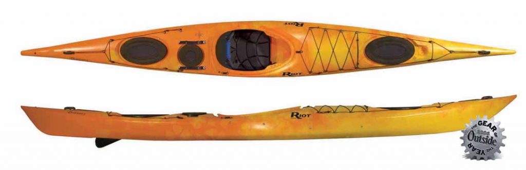
One of my early designs, the Riot Brittany, won Outside Magazine’s “Gear of the Year” award in 2006
A kayak is also an amalgamate of parts produced in various materials, each with their own processes and requirements. High-precision injection-molded plastic fittings and elastomeric parts must fit and seal rotomolded and composite shells equally well, vacuum-formed seating components must be forced through the cockpit and properly recover their shape to perform their task of providing comfort while structuring the hull, etc. There is so much more to it than meets the eye.
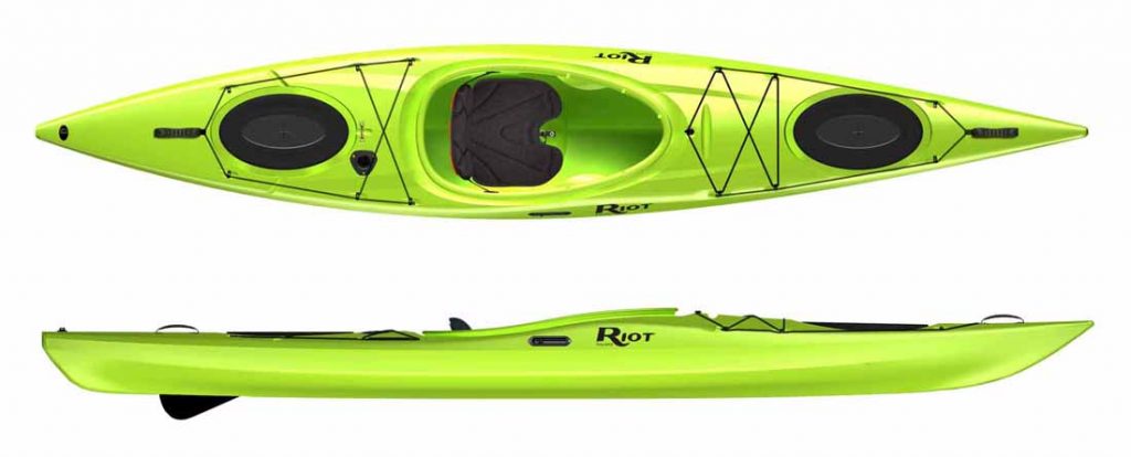
The Riot Edge series was issued in 2009 and remains a popular choice to this day
The modeling of the shell is always a great pleasure to work on, bringing its own set of challenges from streamlining and blending shapes to integrating functional elements so they perform the intended task without hurting the overall look and feel.
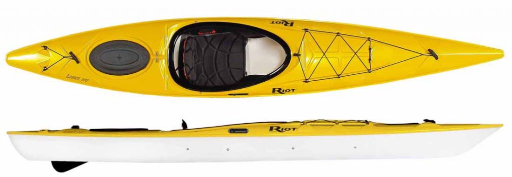
Steve Fisher, testing an early prototype of what would become the Riot Astro. Photo Desré Pickers
Through the years I have developed a unique workflow to address the various aspects of such projects in measurable and verifiable ways, ensuring the performances and safety requirements are met without the need for costly prototyping iterations.
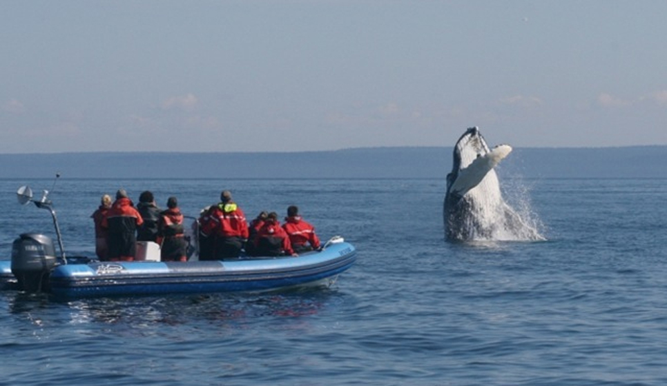
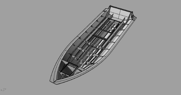
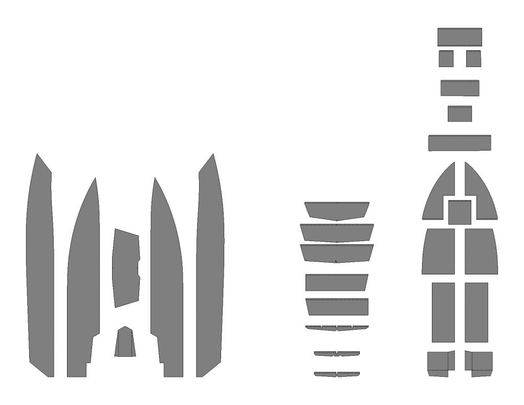
I occasionally work on small motor vessels as well, such as the redesign of this 24-foot commercial rigid inflatable for aluminum construction, and a range of low-draft runabouts designed specifically for low water use, such as the Lachine Rapids, in Montreal.
The finished boat, in action in the St-Lawrence estuary
Overview of the aluminum structure for the 24′ RIB project
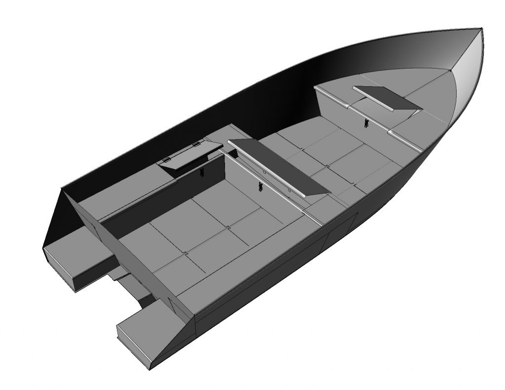
plates of 19′ low-draft runabout
Low-draft, jet-powered 19′ runabout for aluminum construction. Design by Normand Bachand
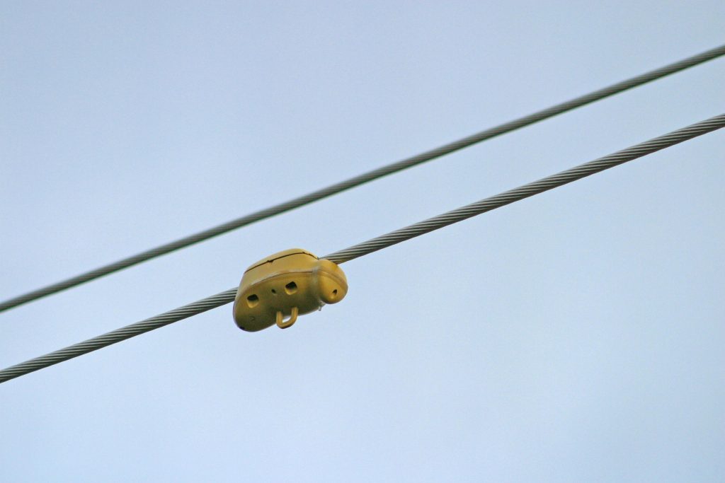
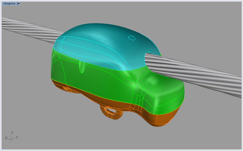
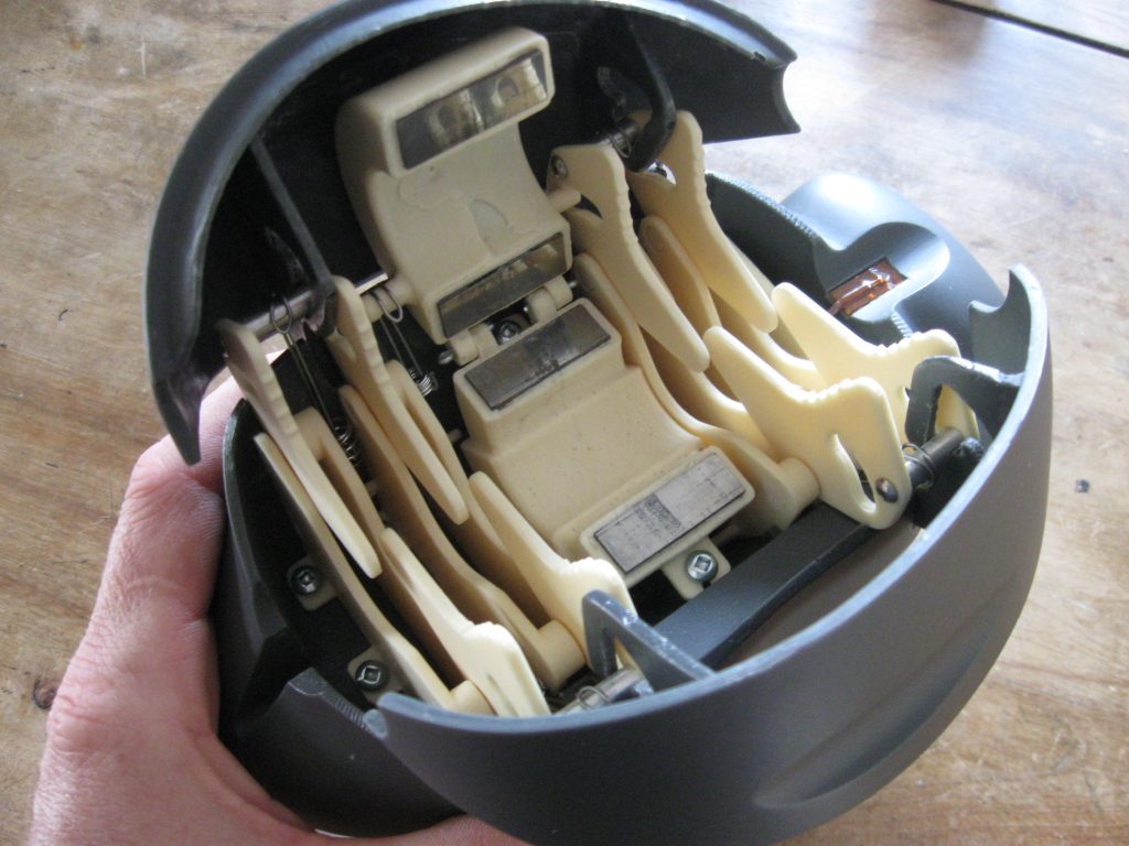
A good example involving high-requirements functional prototyping is a powerline monitor system designed for Maple Microsystems in Ottawa. Right from the beginning there was already a clear vision for the final looks: the silhouette of the final concept should evoke a bee. Once deployed, these overhead devices are quite visible since they are clamped around powerlines and the lump easily catches the eye. The bee shape provided some natural harmony to the inevitable visual disturbance, while it cleverly distinguished MapleBee from the competition in the blink of an eye.
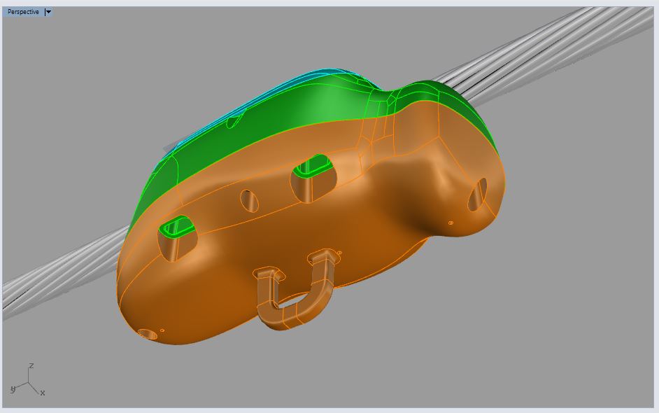
The mechanical requirements also provided an interesting challenge: the clamping system inside the wings of the bee would have to adapt to a wide range of cable diameters. It had to include an induction clamp, a temperature probe and all that had to resist the wide range of weather conditions Ottawa can go through in a full seasonal cycle. The strength of the clamp mechanism had to keep the thing up there no matter how strong the wind, yet allow the device to be pulled off and pushed on the line by utility staff working from the ground with a telescopic perch.
A
B
C
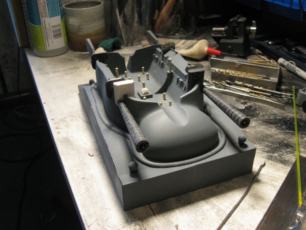
A: Perspective view of the CAD, with color separation to distinguish each component. B: another view showing the drainage pipes of the clamp bay. C: Example of a mold pattern, with all inserts in place. These inserts produce holes for fasteners, locate hinge axis, guide internal wiring and help locate components during assembly.
The functional aspects were tackled first and various solutions were envisioned and tested for the clamp system to adapt to the diameter of the cable. The product being designed for mass production in injection molding, prototypes were cast in high impact, high-temperature polyurethane and epoxy resins, using the projected form factor and assembly solutions.
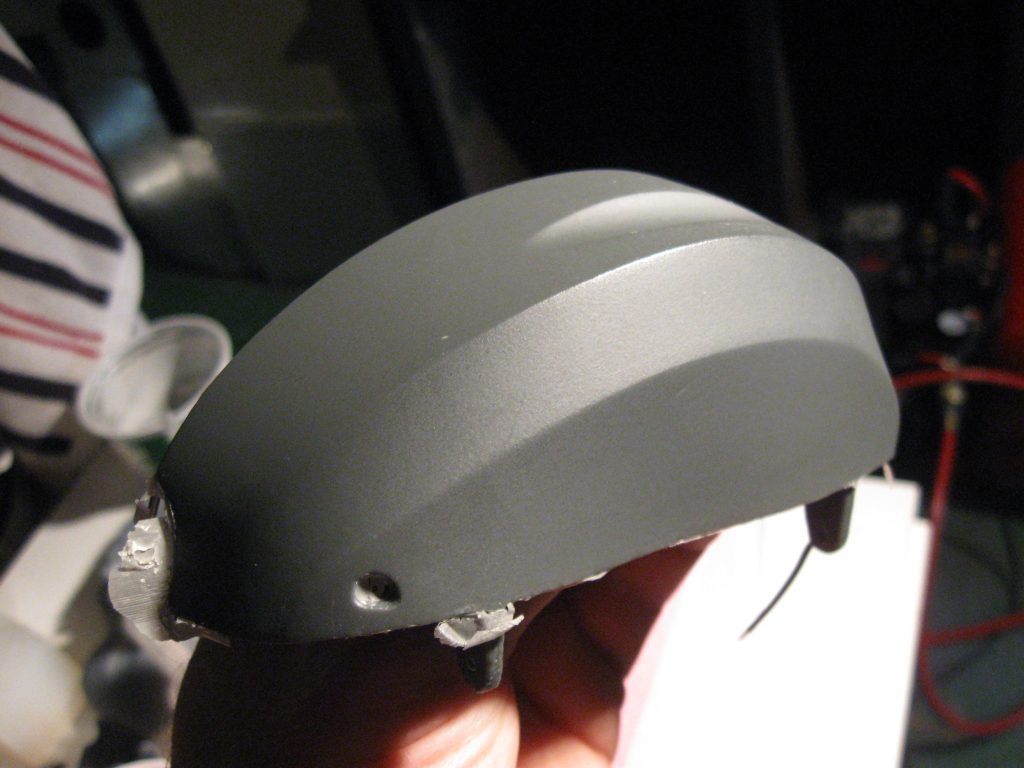
Pictures showing details of an early version. From left to right: A left wing just released from the mold, before finishing. Note how the texture portrays well injection molding / sideview with wings open / internal view of the clamp bay. Despite the apparent complexity, this system uses only four different parts, including two for the induction clamp housing.
Functional prototypes for harsh environments are very interesting projects. While conveying the look-and-feel of the final product, their properties must also be close to the final materials, so results of functional verifications can be trusted. That involves selecting the right resin for each application, and carefully controlling casting and curing conditions.
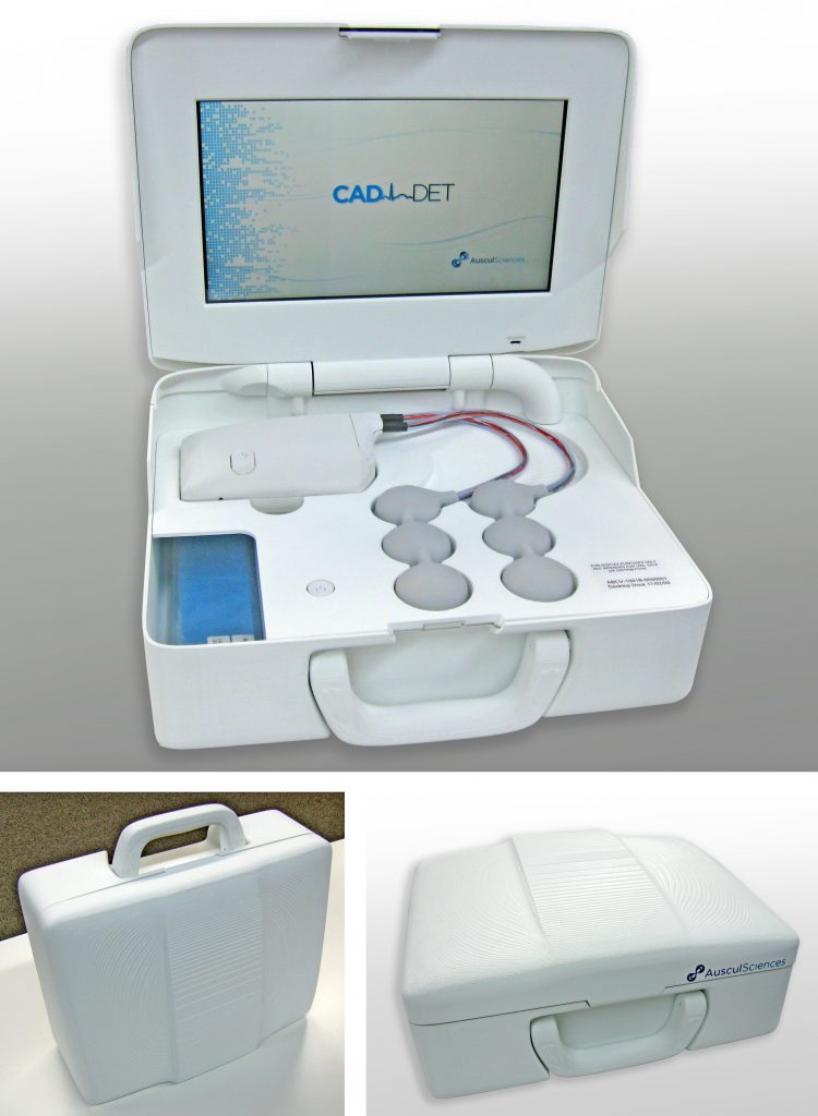
I worked at AusculSciences for almost five years, during which five iterations of the CAD-det System were developed and built within a strict regulatory environment. The company was certified ISO13485:2016 and MDSAP.
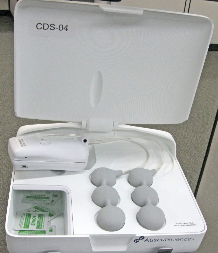
The CAD-det system consisted in a docking station, desktop or mobile, and a small recording module hooked to an array of acoustic sensors. The device was used to detect Coronary Artery Diseases by sound, in an effort to provide a non-invasive, stress-free solution to quickly assess a patient’s heart condition.
One of the portable / desktop iterations of AusculSciences’ CAD-det System
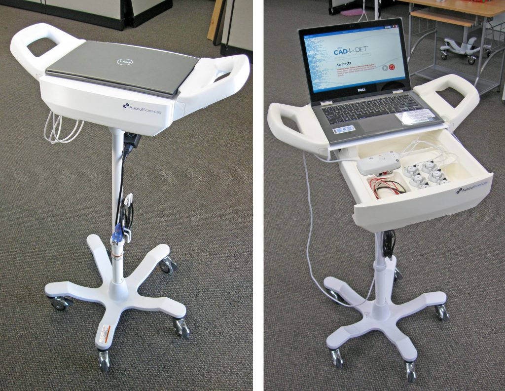
Mobile version of the CAD-det system. Over twenty five units of this model were built, then deployed in various hospitals across Canada for clinical investigation protocols.
The first few iterations of the system were essentially concentrating on validating the technology. One of the main challenges was to procure a maximum freedom of placement to the clinical engineering team, so they could determine the proper location of each of the six sensors on the patient chest. These devices had to remain attached to the patient without anyone holding them in place. That and patient comfort required a low weight and a small size, and the wiring had to be as supple as possible to avoid putting any strain on the critical attachment of the sensors. The first few iterations were overmolded in silicone, as a means of combining these physical requirements with the need for a skin-safe, easy-to-clean material.
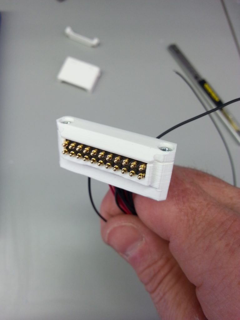
Another aspect was the quantity of conductors running between the Recording Module and the sensors: cables with 12 or 18 core conductors are not very supple, and the problem of dividing this bundle to give each sensor some degree of freedom added to the complexity of using standard products. The connectors also a problem, because of the small dimensions we were targeting, but especially because we had to connect-disconnect the system while it was attached to the patient. Thus no push-pull, latching or rotary connector was really suitable. So I ended up designing and fabricating our own cables and connectors.
22-pins custom connector
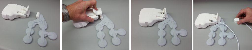
Initial version of the Recording Module and Sensor Assembly: the main connector was grabbed by a self-aligning clamp attached to the front of the module, enabling the user to install and remove the recording module without disturbing the position of the sensor assembly, and without applying undue force on the patient thorax. This version of the system had seven built-in sensors in predetermined locations, and an eighth optional floating sensor that could be positioned anywhere on the chest.
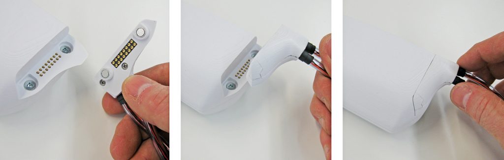
In later versions, the emphasis was put on further easing connection / disconnection, and more flexibility of the sensor assemblies were also requested, so a custom magnetic connector was designed, and the cabling solution was revised to allow more movement to the sensors by splitting them into two groups of three. The picture below shows an example of that sensor design, in yet another iteration of the mobile docking system.
The recording module’s 16-pins custom connector used the housing assembly screws as target pads for the magnets. When in place the connector would hide the fasteners, making for sleek look. Its shape was an assymetrical cutout taken directly off the RM’s overall shape, so its orientation was obvious and it made reversed connection impossible.
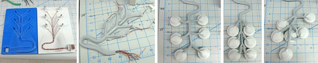
Then in another version the sensors were all separated to provide maximum freedom of placement:
From left to right: the mold ready for casting with conductors installed / The ultrasoft silicone-cast cable harness / A series of three pictures demonstrating freedom of placement. Each sensor had its own magnetic connector that could swivel 360° without affecting the connection.
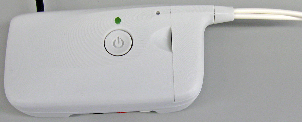
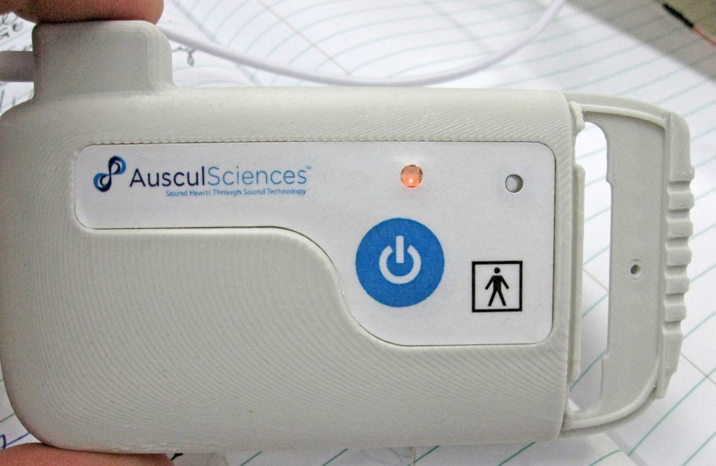
The Recording module and sensors having to be attached to the patient skin, it was important for their shape to convey a sleek, friendly and comfortable look. So a fairly soft overall style was favored. A few hard edges were also used to integrate the wiring flow into the global shape of the module, and to frame the controls area by simply casting shadows on locations where user manipulations would be required.
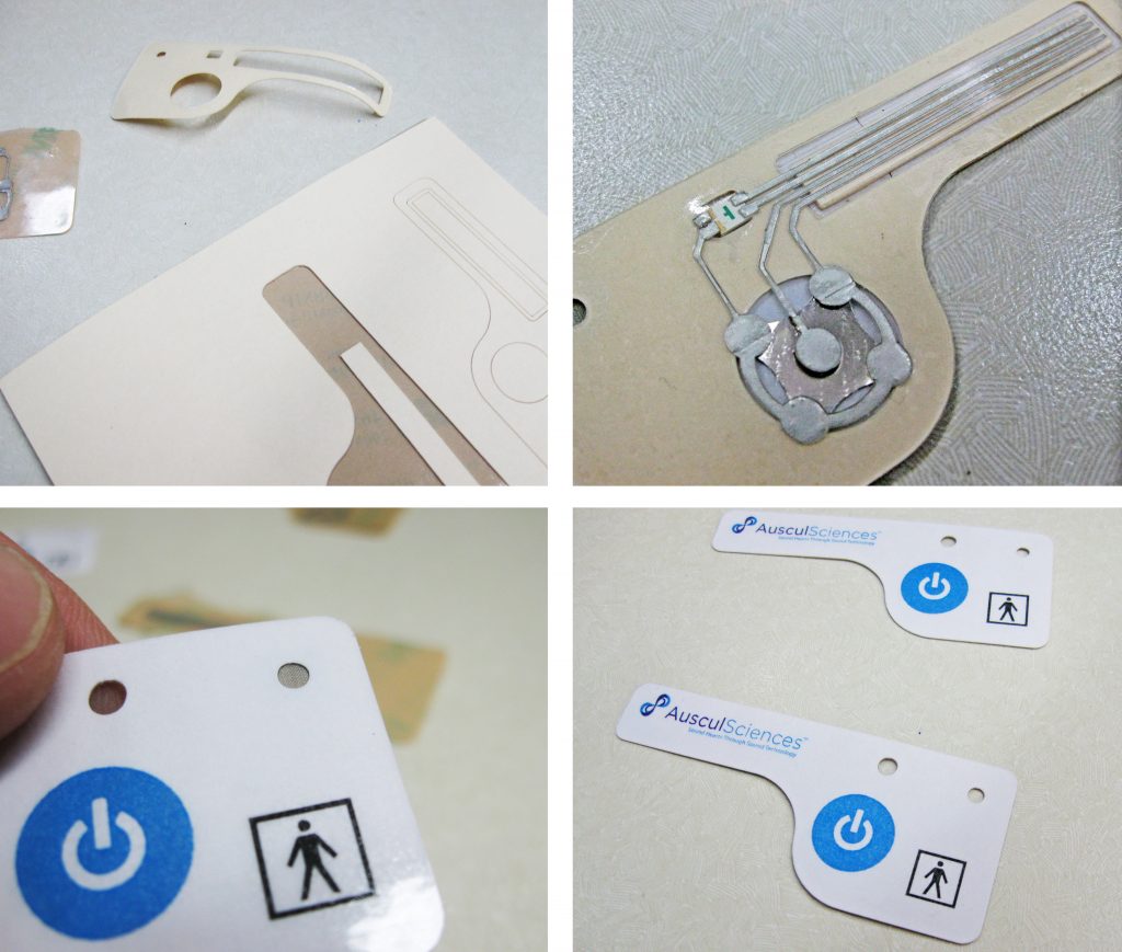
Later on, once the design became stable, the control area was equipped with a membrane-switch integrating a bi-color LED, a mesh screen for microphone protection and some elements of the regulatory labeling. Below are some images of the in-house prototyping phase. The membrane was later produced in series.
This enclosure was designed to house a range of mid-size portable field instruments NDB Technologies had developed over many years for diverse applications, and that bore no resemblance to one another. These were specialized instruments and the annual sales were steady but not in numbers to justify investing in an injection mold. Or so it seemed.
The cost of machining each of the existing housings, if the quantities were to augment, would eventually compare with the initial cost of having an injection mold made. So the idea was to design a platform of a few injection-molded enclosures that would each accomodate a number of the instruments in the actual offering. That modular approach allowed to justify the financial aspect by combining all the instrument sales quantities, and provided an initial template for future developments as well. The largest board outline, top and bottom clearance were already determined, as well as the blank areas that allowed drillings in the side walls. This would greatly help future layouts, choosing connectors, and so on.
The housing was intentionally designed with limited molded-in features, and provided options for easy secondary operations to be performed in-house so instruments could be built on order. Another important effect of these choices was to create an identity around NDB’s family of products.
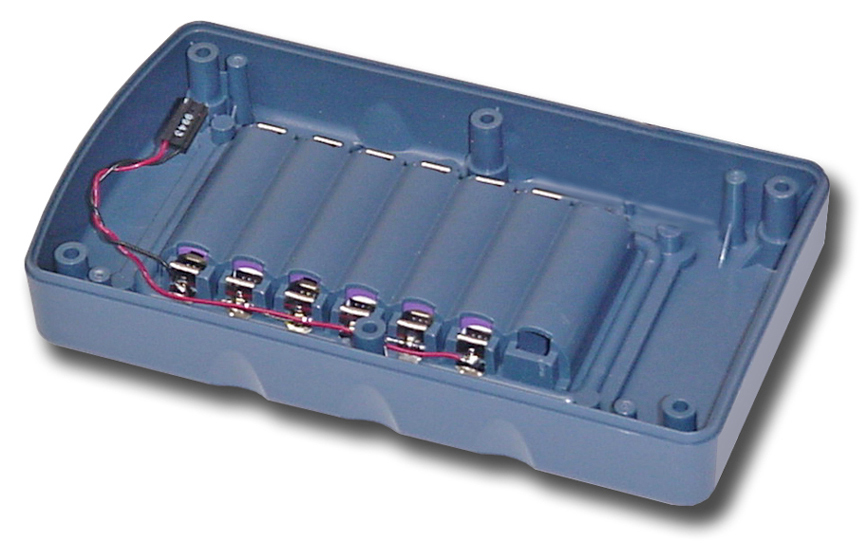
Bottom half of mid-size housing showing battery bay
The modular approach extended to internal features like the battery bay, where a specific number of battery clips were wired and installed according to an instrument’s specific power requirements. The batteries being rechargeable this was transparent to the users and the batteries could be replaced during routine servicing by unscrewing the watertight rear door.
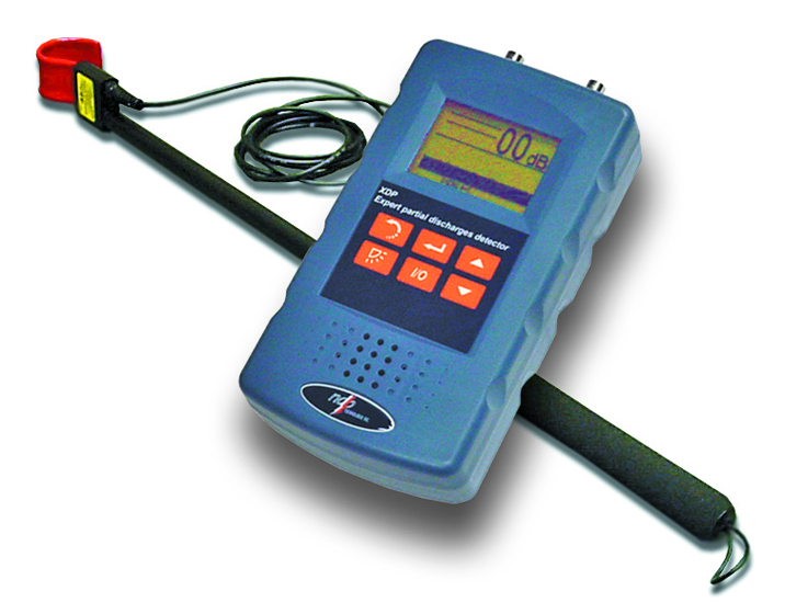
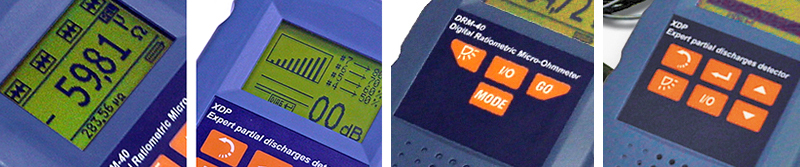
The user interface was composed of a small LCD screen and a membrane-switch which basic template allowed for up to 9 large-size buttons. The color schemes were done in accordance with NDB’s “look and feel”, with a combination of contrasting orange/blue scheme, enhancing visibility. The pictograms used were also standardized so the indicators of similar functions would remain consistent across the company’s products.
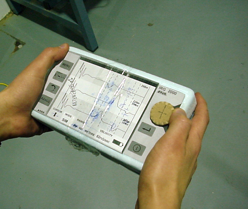
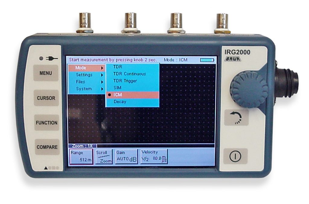
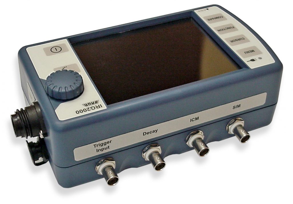
The housing’s modular approach allowed later expansion by creating a new faceplate based on the specific needs of a new project, without having to create an entirely new enclosure. An example of an alternate choice was the IRG2000, a powerline diagnostics instrument developed for Baur in Austria. It required a more elaborate graphic interface, with a means of navigating various menus while holding the instrument. The orientation was changed to horizontal, and a clickable knob was chosen to ease operation.
Verification of projected thickness and positioning of controls. Prototypes are not always expensive!
This illustrates how a bit of forethought can go a long way. Projects seemingly out of reach may actually make good business sense much earlier than expected, when carefully planned and iteratively executed.