I worked at AusculSciences for almost five years, during which five iterations of the CAD-det System were developed and built within a strict regulatory environment. The company was certified ISO13485:2016 and MDSAP.
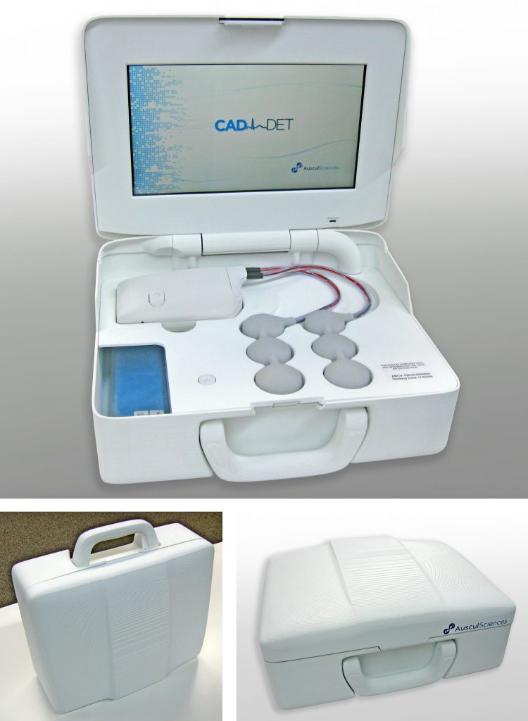
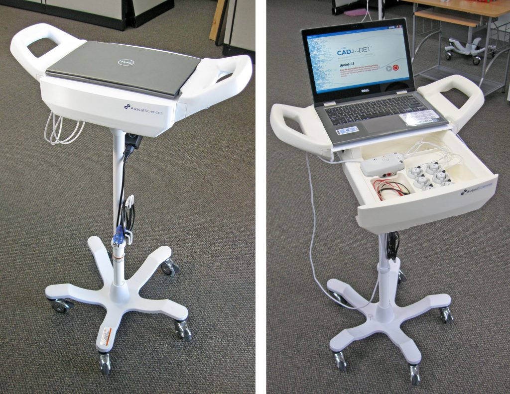
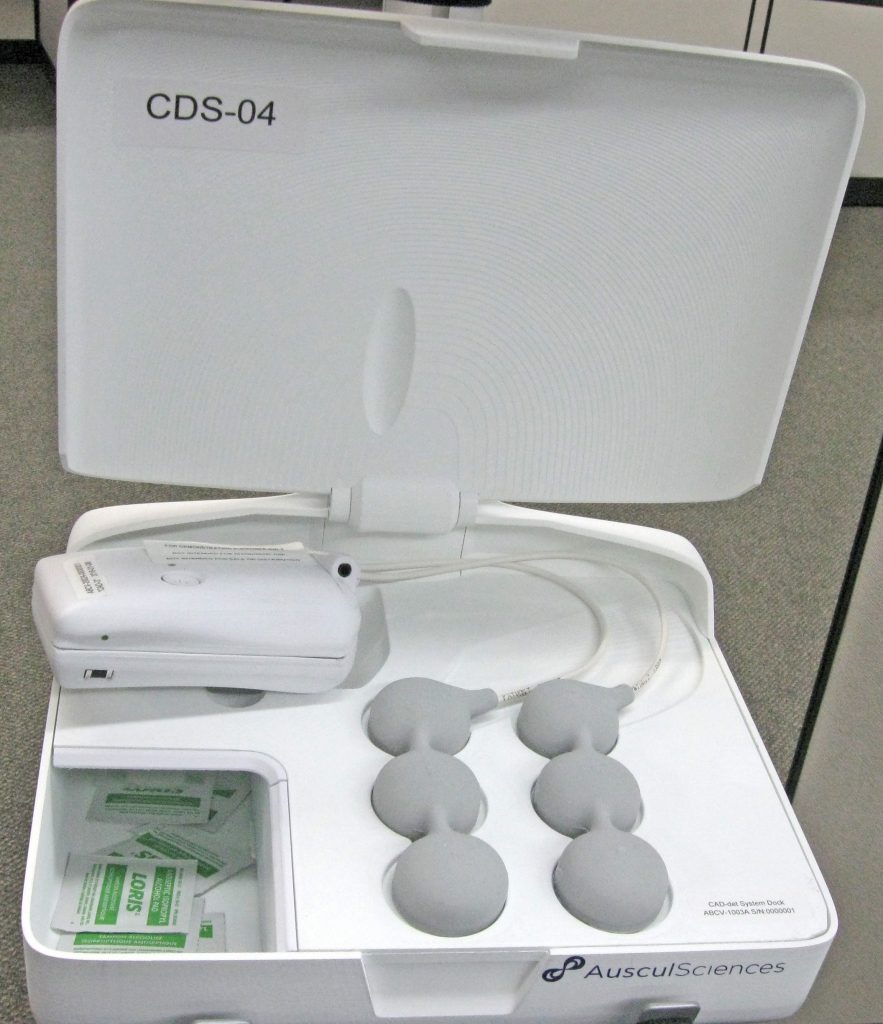
The CAD-det system consisted in a docking station, desktop or mobile, and a small recording module hooked to an array of acoustic sensors. The device was used to detect Coronary Artery Diseases by sound, in an effort to provide a non-invasive, stress-free solution to quickly assess a patient’s heart condition.
The first few iterations of the system were essentially concentrating on validating the technology. One of the main challenges was to procure a maximum freedom of placement to the clinical engineering team, so they could determine the proper location of each of the six sensors on the patient chest. These devices had to remain attached to the patient without anyone holding them in place. That and patient comfort required a low weight and a small size, and the wiring had to be as supple as possible to avoid putting any strain on the critical attachment of the sensors. The first few iterations were overmolded in silicone, as a means of combining these physical requirements with the need for a skin-safe, easy-to-clean material.
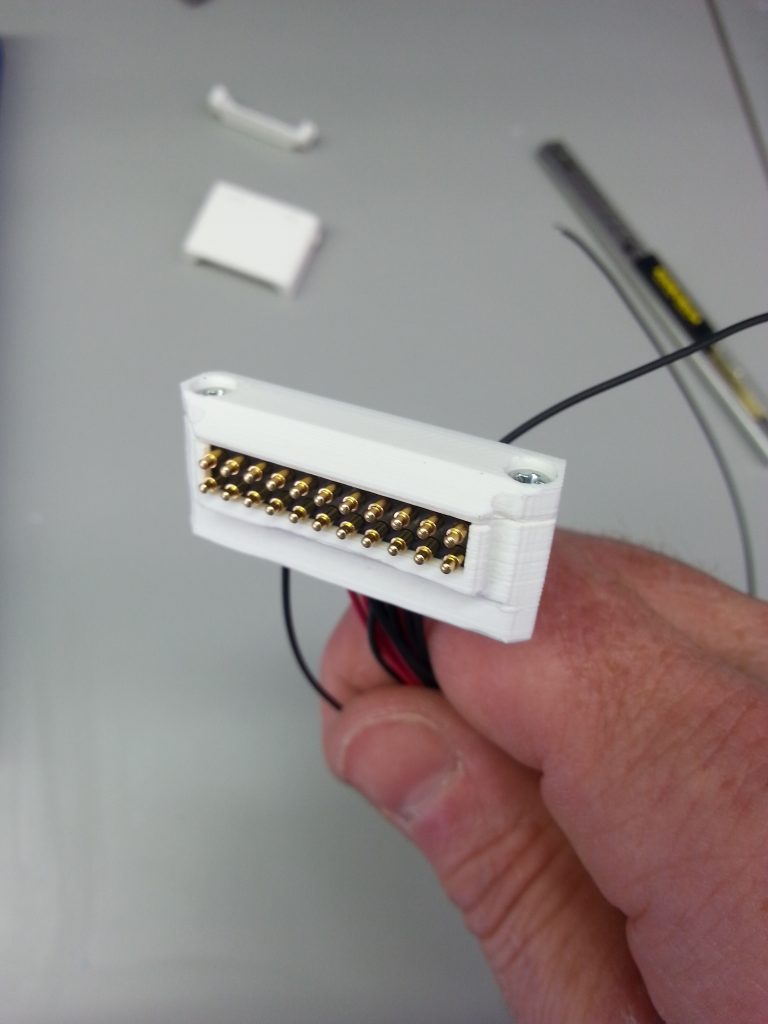
Another aspect was the quantity of conductors running between the Recording Module and the sensors: cables with 12 or 18 core conductors are not very supple, and the problem of dividing this bundle to give each sensor some degree of freedom added to the complexity of using standard products. The connectors also a problem, because of the small dimensions we were targeting, but especially because we had to connect-disconnect the system while it was attached to the patient. Thus no push-pull, latching or rotary connector was really suitable. So I ended up designing and fabricating our own cables and connectors.
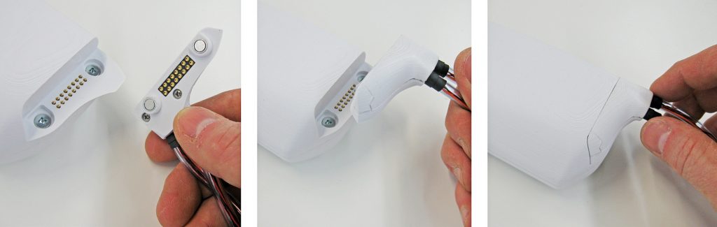
In later versions, the emphasis was put on further easing connection / disconnection, and more flexibility of the sensor assemblies were also requested, so a custom magnetic connector was designed, and the cabling solution was revised to allow more movement to the sensors by splitting them into two groups of three. The picture below shows an example of that sensor design, in yet another iteration of the mobile docking system.
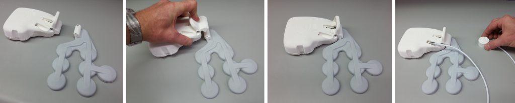
Then in another version the sensors were all separated to provide maximum freedom of placement:
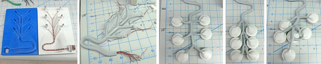
the mold ready for casting with conductors installed / The ultrasoft silicone-cast cable harness / A series of three pictures demonstrating freedom of placement.
Each sensor had its own magnetic connector that could swivel 360° without affecting the connection.
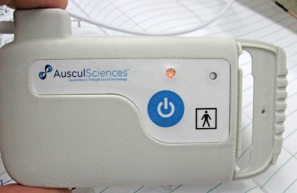
The Recording module and sensors having to be attached to the patient skin, it was important for their shape to convey a sleek, friendly and comfortable look. So a fairly soft overall style was favored. A few hard edges were also used to integrate the wiring flow into the global shape of the module, and to frame the controls area by simply casting shadows on locations where user manipulations would be required.
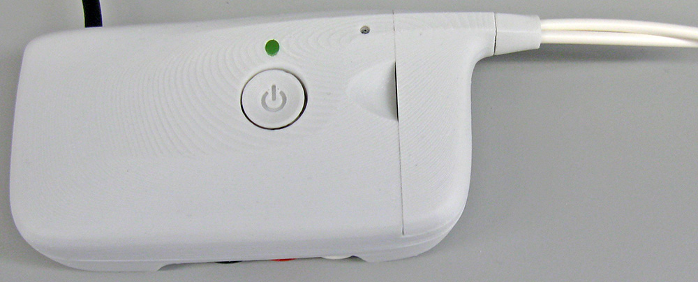
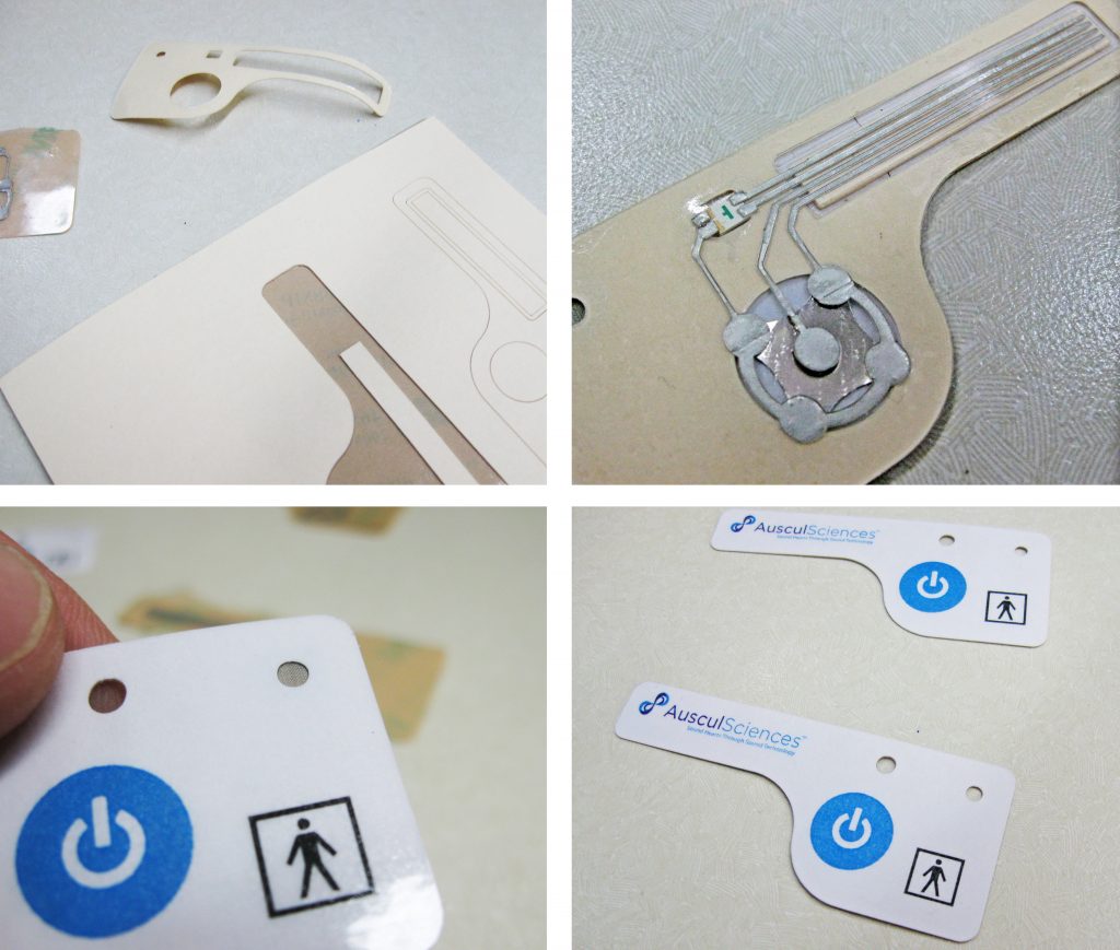
Later on, once the design became stable, the control area was equipped with a membrane-switch integrating a bi-color LED, a mesh screen for microphone protection and some elements of the regulatory labeling. Below are some images of the in-house prototyping phase. The membrane was later produced in series.